
What is VLAN?
Imagine a bustling city with numerous districts. Each district represents a physical LAN, where devices like computers and printers reside. People within a district can easily communicate with each other, but reaching someone in another district requires extra effort.
VLANs (Virtual LANs) come in like invisible city walls, creating logical subdivisions within a physical LAN. Think of them as smaller, more focused neighborhoods within the larger city. Devices assigned to the same VLAN can freely communicate, but they’re walled off from devices in other VLANs, just like residents of different neighborhoods wouldn’t normally interact directly.
This segregation offers several advantages:
- Increased Security: Confidential data or sensitive devices within a VLAN stay protected from unauthorized access from other VLANs. Imagine a finance department in its own VLAN, isolated from the marketing department. If VLAN is set up in a homelab, it can help isolate devices from other risky devices on guest wifi. Valid usages includes iOT devices and cctv cameras.
- Improved Performance: By reducing unnecessary broadcast traffic like ARP and DHCP, VLANs free up network resources, leading to smoother performance for all devices. Think of rush hour traffic being diverted to specific lanes, making the overall flow smoother.
- Enhanced Manageability: Network administrators can easily control and monitor traffic flow within each VLAN, making it easier to troubleshoot problems and optimize network usage. Imagine having dedicated city inspectors for each neighborhood, ensuring everything runs smoothly.
Vlan introduces a logical layer beyond a physical LAN that increases the amount of broadcast domains in order to manage traffic and harden network security. Here’s an analogy to illustrate the difference between a regular LAN and a VLAN with increased broadcast domains:
Regular LAN: Imagine a school cafeteria where everyone shouts announcements to everyone else. This is inefficient and noisy!
VLAN with increased broadcast domains: Now imagine the cafeteria divided into smaller sections, each with its own speaker system. Announcements are only made within each section, creating a quieter and more organized environment.
By increasing the number of broadcast domains through VLANs, we essentially create these smaller, more focused sections within the network, leading to the benefits mentioned earlier.
Important:

• Native LAN: Ethernet VLAN devices treat all untagged frames as belonging to the native LAN by default when traversing on 802.1q trunk interfaces. Created for backward compatibility for old devices that don’t support VLANS.
The native LAN is VLAN 1, administrators can change this native VLAN number. It is a security best practice to configure all the ports on all switches to be associated with VLANs other than VLAN 1 to avoid VLAN hopping attack.

*It is also a good practice to shut down unused switch ports to prevent unauthorized access.
*If connecting two switches, make sure Native VLAN is the same on both ends to ensure no mismatch and all frames are untagged.
*If setting up router on a stick (ROAS)- Switch to router, native Vlan can be left alone as Routers do not understand native VLAN ID. The router will view any incoming frames as untagged. All it needs to know is what other VLANs need to be tagged, which is learned via configuration of sub interfaces.
*CDP, VTP,STP traffic requires a native VLAN.

• Default VLAN - Default VLAN will always be VLAN 1, it cannot be changed or deleted. Interfaces will be placed in the default vlan 1 if there is no Vlan configurations. Default VLAN is NOT the same as native vlan.

• Management VLAN:  Supports remote connections from network administrators. Some networks use VLAN 1 as the management VLAN, while others set up a special number for this purpose (to avoid conflicting with other network traffic). A good security practice is to separate management and user data traffic. The management VLAN, which is VLAN 1 by default, should be changed to a separate, distinct VLAN. To communicate remotely with the switch for management purposes, the switch must have an IP address configured on the management VLAN. Users in other VLANs would not be able to establish remote access sessions to the switch unless they were routed into the management VLAN or via jump server
Setting up VLAN in home lab requires a device with Opnsense and a layer 2 switch. User can also use a layer3 switch.
The Lab environment will look like this:
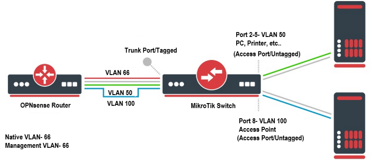
Goal:
- Create VLAN 50 for PC and printers.
- Create Management VLAN 66 to manage the switch and other devices.
- Create a VLAN 100 for guest WIFI.
*The alternative option is to directly connect the AP to the OPNsense box if its equipped with a 4 port NIC. This isolates the wifi traffic to only that port with a new network address, but it is a boring setup as it does not involve any tagging. The configuration would be too simple.
In this lab, we will utilize the cool feature of traffic tagging on Opnsense and MikroTik devices.
** Make sure the Netgear router is in AP mode. Not router or bridged mode. Bridge mode turns a secondary router to function as a switch, extending the LAN ports for devices to be connected.
From OPNSense:
1. Create the sub interface first:
Interface > Other types > VLAN > add “+” > Add VLAN 50, 66 ,100
We will use re0 as parent interface. The re0 interface is the LAN port on the computer installed with Opnsense.

2. Assign VLAN to Parent interface:
Interface > assignment > select the vlan and pick re0 to add it.

3. Enable VLAN interface:
Interfaces > vlan50 > enable interface
Set address to 192.168.50.1/24 to be gateway/management
Interfaces > vlan66 > enable interface
Set address to 192.168.66.1/24 to be gateway/management
Interfaces > vlan100 > enable interface
Set address to 192.168.100.1/24 to be gateway/management

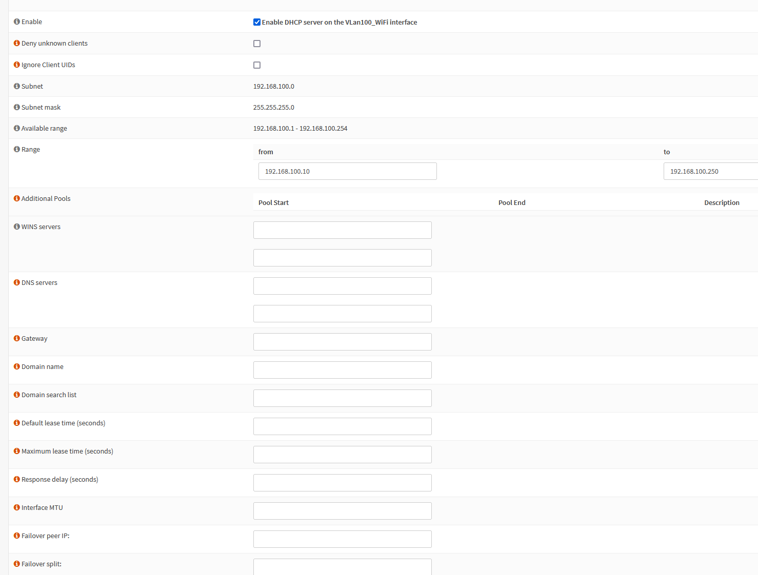
4. Enable DHCP on VLAN sub interface
Services > DHCPv4 > VLan50 > enable DHCP
Range: 192.168.50.10 – 192.168.50.250
Services > DHCPv4 > VLan66 > enable DHCP
Range: 192.168.66.10 – 192.168.66.250
Services > DHCPv4 > VLan100 > enable DHCP
Range: 192.168.100.10 – 192.168.100.250
Set your DHCP range and DNS address. I suggest configuring unbound DNS later to use Quad9 nameserver so leave the DNS field empty.
5. Firewall rules
Set rules to isolate wifi guest network from talking to devices on LAN (192.168.1.0/24), VLAN 50 (192.168.50.0/24) and 66 (192.168.66.0/24).
Also block port 22/80/443 access to Opnsense portal across all sub interfaces (192.168.1.1, 192.168.50.1, 192.168.66.1, 192.168.100.1)
**The rules will block traffic going IN to other VLAN devices but it does not prevent devices on other Vlan to communicate with Wifi devices. This is a one way block, not both ways.
** Always enable the [Allow Vlan Network] rule last since OPNsense process whichever rule is listed at the top first.
** Isolate other VLAN if desire with the same rules.

MikroTik Layer 2 switch (mikrotik css610-8g-2s+in) switchOS lite
Once the router part is completed. The only thing left to do is to assign VLAN 50, 66 and 100 to the appropriate ports on the switch and toggle untagged (Access) or tagged (Trunk) mode.
Create the VLAN assignment on the switch:
1. VLans > select append
2. Vlan 50 will be assigned to port 1-6  (PC, printers, etc will be plugged into here)
3. Vlan 66 to port 1 and port 7 (Plug device to port 7 to access management gui)
4. Vlan 100 to Port 1 and port 8 (Plug in Access Point to Port 8)
*Port 1 will be the OPNsense box

Configure Trunk and access ports:
Port 1 is where the link between switch and Opnsense box, configure this to be [strict/only tagged] to set it as TRUNK port with Native Vlan 66.
Port 2-8- all other ports can be configure as Strict/Only Untagged- Access Port, Assign the appropriate VLAN ID.
*If setting port 1 to strict/only tagged, it will automatically drop any native vlan packets for ports not assigned a vlan ID like Vlan 1. Resulting in transmit failed general failure. This setup REQUIRES the port to have VLAN ID other than 1 to be set or the device will not communicate.


Results:
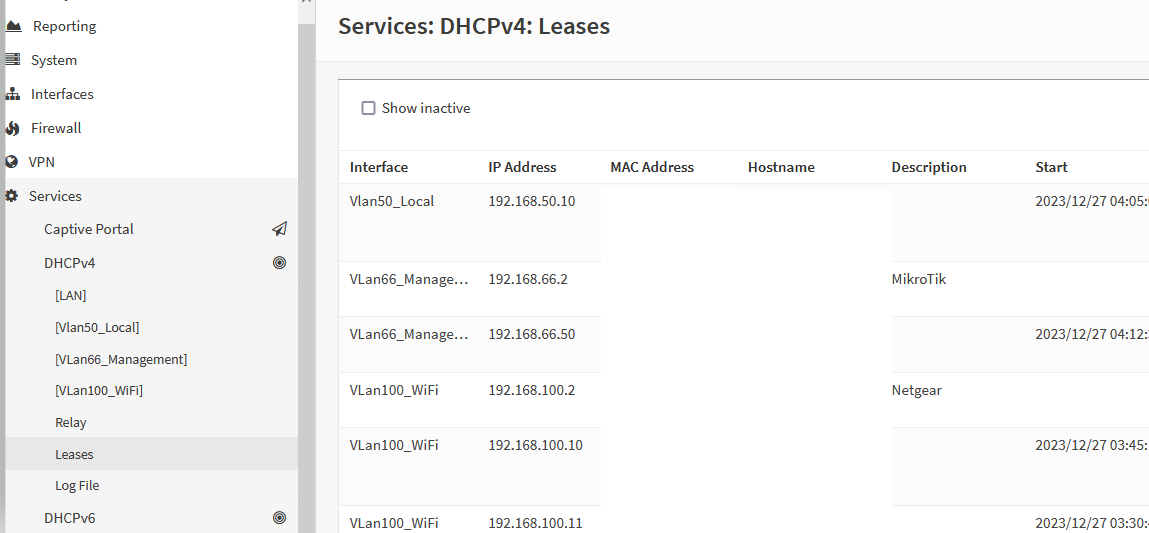
Plug any device into Port 2-6, and it will receive 192.168.50.0/24 address.
Plug any device into Port 7 to have it be on management vlan (192.168.66.0/24). Which opens access to administration task. A jump server can be created on this VLAN to segment and audit traffic if desire.
Plug netgear AP into port 8 and the device connected to the wireless router will get the lease from the DHCP running on interface Vlan0.100 with address of 192.168.100.0/24
If a user plugs a device into a port with Default VLAN 1 and VLAN mode set to strict or optional - The device will NOT get an IP. The port is essentially a black hole.

**Make sure the router is in AP mode. Not router or bridged mode.
*Device in the VLAN 100 network will not be able to communicate with devices on any other VLAN or access OPNsense GUI due to firewall restrictions.
Management (Optional):
Restrict access to MikroTik switch from specific VLAN or ports if desire

Source:
https://www.zenarmor.com/docs/network-security-tutorials/how-to-configure-vlan-on-opnsense
https://help.mikrotik.com/docs/display/SWOS/CSS610+series+Manual#CSS610seriesManual-VLANandVLANs
https://docs.opnsense.org/manual/other-interfaces.html#vlan
https://www.packetswitch.co.uk/what-is-a-native-vlan-and-how-does-it-work/
